Advanced Industrial
Scope
Provide support for SDI-12, 4-20mA and pulse input sensors with flexible configurations. It is applicable to Agriculture & Environmental Monitoring applications.
General Information
| Host board | insigh.io main board |
| Version | v1.2.0 |
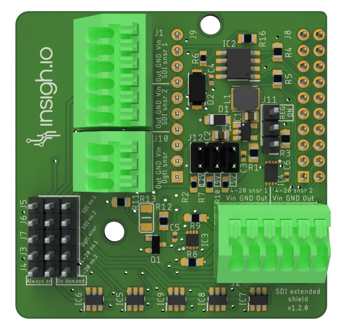
| Supported Digital Interfaces | 2 x SDI-12 & 2 x 4-20mA & 1 x Pulse Counter |
| Sensor Headers | Fixed Terminal Block with push-in connection (no tools required) |
| 1x8-pin (SDI-12 & Pulse Counter) & 1x6-pin (4-20mA) | |
| Dimensions (L x W x H) | 41.3 x 47 x 16.7 mm |
| Weight | 16 g |
Example Applications
- Precision Agriculture
- Soil moisture, Electrical Conductivity, Volumetric Water Content, Temperature
- Environmental monitoring
- Water flow, water quality, Temperature, Humidity
Sensors Support (Hardware & Software)
Common Features
| Supply Voltage | 5V/9V/12V DC (selected via jumper) |
| Operation Modes | Jumper J11 for controlling the board power mode through (“REG ON”) |
| Jumper J12 for controlling supply voltage (5V/9V/12V) | |
| Jumpers J3 & J7 for controlling the sensor power mode for each sensor independently | |
| Maximum Drawn Current | 300 mA |
SDI-12 Interface
| Number of Sensor Ports | 5 (simultaneously), 3 pins (POWER,DATA,GND) each |
| Sensors Software Support | General SDI-12 Commands Implementation (C, M) |
| Built-in Firmware | Fully tested against the following models: TEROS-12 (METER), TDR-315H (ACCLIMA), Sap Flow (IMPLEXX), LI-710 (LI-COR), Shandong Renke Weather (Weather), ATMOS 41 (METER), Aquatroll Water Sensor (In situ) |
4-20mA Interface
| Number of Supported Sensors | 2 x 2-wire or 4-wire |
| Sensors Software Support | Sensor-agnostic, using a 2-channel analogue current sensing circuit |
| Built-in Firmware | Fully tested with Ground Water Pressure Sensor PR26Y (KEPLER)) |
Generic Digital Interface
| Number of Supported Sensors | 1 |
| Supply Voltage | No, the sensor should be externally powered) |
| Typical Usage | Pulse Counter |
| Advanced Features | Ultra-Low Power Operation Option for background pulse recording |
Operation Modes
Board Power mode
There are 2 “power"supply modes for the shield controlled via the PCB hardware. These modes are applied over all sensors.
- “Heating” mode: It applies continuous DC voltage (5V/9V/12V) even at deep sleep. This is required by some sensors for condensation avoidance (e.g. Oxygen Sensor SO-411 from Apogee) or special measurement procedure (e.g. Evapotranspiration Sensor which requires 30 min averaging or ATMOS41). To enable this, place the J11 jumper mode to “REG_ON” position.
- “Low-power” mode: This is a mode optimized for energy consumption. To enable this place the J11 jumper to the bottom position. In this mode, the sensors are powered only during the micro-controller wake-up periods by enabling a special control pin from the firmware, i.e. IO37.
Supply voltage
The shield supports 3 different supply voltages for the sensors, namely 5V, 9V, and 12V. These can be selected via the J12 jumpers set. By default (if no jumper is set) the board provides 5V.
Sensor Power mode
In addition, with the use of Jumpers the user may control each sensor’s power mode independently. There are 5 jumper sets:
- J5 & J6 controls the SDI-12 Sensor Port 1 and 2 respectively
- J3 & J4 controls the 4-20mA Sensor Port 1 and 2 respectively
- J7 controls the single Digital Port
The operation is controlled as follows:
- If jumpers enable the “always-on” mode (left-center pins), then the sensor data can be accessed continuously.
- If jumpers enable the “on-demand” mode (center-right pins), then the sensor data can be accessed only when the proper control pin is enabled.
“On-demand” mode is the most energy-efficient one. The control pins are:
- SDI-12 Sensors: IO42 & IO48 for Port 1 & Port 2 respectively
- 4-20mA Sensors: IO7 & IO8 for Port 1 & Port 2 respectively
- Pulse Counter Sensor: IO6
4-20mA Sensors Connection Instructions
Below you may find the proper connection instructions for 2-wire/4-wire sensors in case internal (own board) or external power supply unit is used:
-
Sensor Type: 2-wire
- Power Supply: Internal
- Sensor PWR pin connected to VIN board port
- Sensor OUT pin connected to OUT board port
- Power Supply: External
- Sensor PWR pin connected to External Supply Positive Pin (+)
- Sensor GND pin connected to External Supply Negative Pin (-)
- Sensor OUT pin connected to OUT board port
- Power Supply: Internal
-
Sensor Type: 4-wire
- Power Supply: Internal
- Sensor PWR pin connected to VIN board port
- Sensor 1st GND pin connected to GND board port
- Sensor 2nd GND pin connected to same GND board port
- Sensor OUT pin connected to OUT board port
- Power Supply: External
- Sensor PWR pin connected to External Supply Positive Pin (+)
- Sensor 1st GND pin connected to External Supply Negative Pin (-)
- Sensor 2nd GND pin connected to GND board port
- Sensor OUT pin connected to OUT board port
- Power Supply: Internal
Pulse Counter Ultra Low Power Operation Option
Many devices, like rain gauges or water flow sensors generate one or more pulses when certain liquid volume has been observed. This is different from typical SDI-12 and 4-20mA measurement scenarios, where we need to periodically wake up our IoT device (e.g. once per our hour), take a measurement and then go to deep sleep. Instead, with pulse generating sensors we need to continuously “capture” the pulses while not exhausting battery life. For this purpose we are supporting through firmware version 2.9.0 and on a special operating mode called ULP, which hosts the pulse counting measurement into an ultra-low processor drawing less than 400uA for up to 5kHz pulse frequencies.
Marking
| CE | under way |
| FCC | under way |
| RoHS | under way |
Custom designs
The existing boards are highly configurable and expandable so if the existing boards do not fit your need, get in contact with us and we will tailor a solution for you with your customizations.