v1.0.0
|
|
| Microcontroller |
ESP32-S3-WROOM-1 |
| Modem |
NB-IoT/LTE-M with GSM fallback - Embedded Nano-SIM Holder |
| GNSS |
GPS, BeiDou, Galileo, GLONASS and QZSS |
| Power Supply |
Battery (rechargeable), USB, Solar Panel |
| Onboard Diagnostic Sensors |
Temperature/Humidity based on the SHT40 sensor IC |
| Misc |
Header for firmware flashing/debugging through UART |
|
Power/Debugging through USB (debugging not fully supported yet, use UART instead) |
|
Support for external switch |
| Software |
Micropython (aligned with version 1.19) |
|
Open-source libraries & demo scenarios @ Github |
|
WiFi based Web Configurator wizard |
| Dimensions (L x W x H) (+ WiFi antenna) |
78 (83.5) x 57.2 x 16.7 mm |
| Weight |
28 g |
| Enclosure |
IP65/IP67 |
Example Applications & Sensors Support
- Precision Agriculture/Apiculture
- Soil Moisture, Soil/Water Electrical Conductivity, Weight (beehive)
- Environmental/Industrial monitoring
- Indoor Air quality, Outdoor Temperature & Humidity
- Cyclic Economy
- Asset tracking & Road Quality Detection
- Location, Speed, Acceleration, Magnetometer
Communication
- Wireless technologies
- WiFi
- Bluetooth
- GSM / NB-IoT / LTE-M
- Transport protocols
- TCP/UDP over IPv4/IPv6
- MQTT
- CoAP
Power Supply
|
|
|
|
|
|
| USB |
Port (Port ID) |
Input Voltage |
|
|
|
|
Micro USB (J2) |
Min. |
Typ. |
Max. |
Units |
|
|
4.5 |
5 |
5.5 |
V |
| Battery |
Port (Port ID) |
Nominal Characteristics |
|
|
|
|
JST (J1) |
1 x Rechargeable LiPo 1S1C 3.7-4.2 V |
|
|
|
| Solar Panel |
Port (Port ID) |
Input Voltage |
|
|
|
|
Fixed Terminal Block with push-in connection |
Min. |
Typ. |
Max. |
Units |
|
No tools required (J4) |
5.5 |
6 |
6.5 |
V |
Operating Conditions
|
|
| Microcontroller Operating Voltage |
3.3 V |
| Charging Current Limit |
440 mA |
| Maximum Drawn Current |
3 A |
| Operational Temperature |
0 – 60 C |
| Charging Temperature |
0 – 60 C |
Indication LEDs
Charging State Indication (RED LED)
| Charge cycle state |
LCR LED |
| No input |
OFF |
| Temperature fault |
BLINKING |
| No battery |
BLINKING |
| Charging |
ON |
| Charge complete |
OFF |
Modem State Indication (RED LED)
| Modem state |
LCR LED |
| Disabled |
OFF |
| Network Search |
BLINKING SLOWLY (OFF most of the time) |
| Idle |
BLINKING SLOWLY (ON most of the time) |
| Transferring Data |
BLINKING QUICKLY |
Operational State Indication (RGB LED)
| Operational State |
RGB LED |
| Deep Sleep |
OFF |
| Web UI Loaded (waiting for connection) |
MAGENTA (BLINKING) |
| Booting/Sensors reading |
BLUE |
| Trying to attach to Network |
RED |
| Connected to Network, ready to send data |
GREEN |
Switches
| Switch Name |
Details |
| S1 |
Controls power supply to the micro-controller (the battery charging process is not affected) |
| S2 |
Tactile switch for resetting the micro-controller |
| S3 |
Tactile switch for activating the micro-controller’s bootloader (needed only for fw upgrade) |
| EXT SW |
External latching switch to control micro-controller’s power (the battery charging process is not affected) |
| SNSR_GND |
Electronic software-controlled ground switch for enabling/disabling power supply to sensors on-demand |
Switch combinations & power supply
| External switch (EXT SW - J4) |
On-board switch (S1) |
Circuit |
| Open |
ON |
ON |
| Open |
OFF |
OFF |
| Closed |
ON |
ON |
| Closed |
OFF |
ON |
Energy Consumption Profiling
|
|
| Battery Voltage |
Accurate Measurement of battery voltage even at charging state |
External components required/recommended
- Battery
- Solar Panel
- Flexible Cellular Antenna
- Flexible GPS Antenna
- SIM card
Expansion Capabilities
Sensor Board Expansion
General Description
- Position: Top-right
- Type: 1 x Single-Row (R1) & 1 x 2-row (R2-1 & R2-2) 10-pin Female Socket Header
- Number of exposed pins: 30 x power/analogue/digital pins (IOs)
- Usage
- attaching insigh.io add-on boards
- create custom applications in breadboards
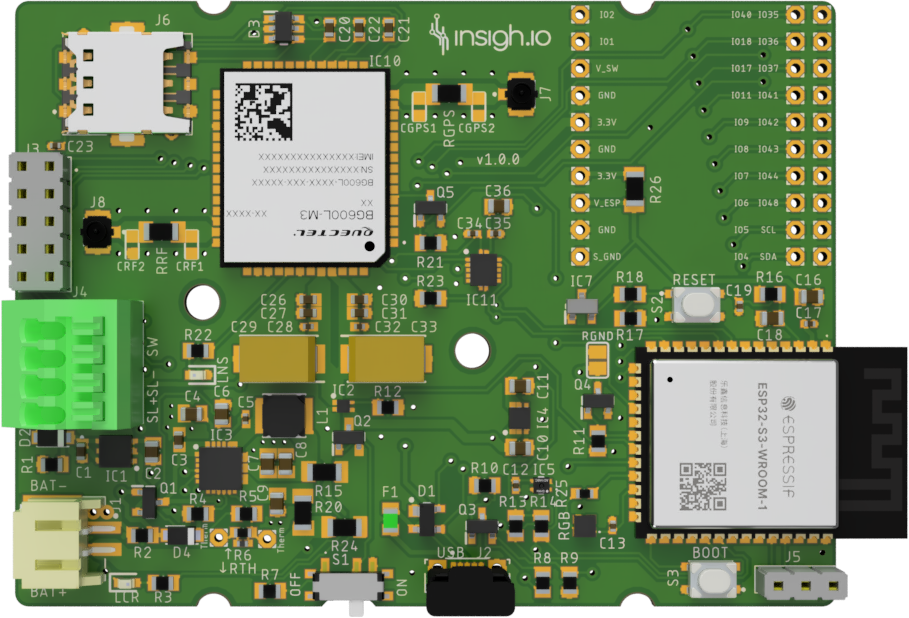
Pins mapping
Note: Orientation as in the board picture
| R1 |
R2-1 |
R2-2 |
| IO2 |
IO40 |
IO35 |
| IO1 |
IO18 |
IO36 |
| V_SW |
IO17 |
IO37 |
| GND |
IO11 |
IO41 |
| 3.3V |
IO9 |
IO42 |
| GND |
IO8 |
IO43 |
| 3.3V |
IO7 |
IO44 |
| V_ESP |
IO6 |
IO48 |
| GND |
IO5 |
SCL |
| S_GND |
IO4 |
SDA |
Pins Description
Note: You could also check the ESP32-S3-WROOM-1 Datasheet for further information on the annotated pins
Radio/GPS Expansion
General Description
- Position: Mid-left
- Type: 1 x 2-row (R3-1 & R3-2) 5-pin Female Socket Header
- Number of exposed pins: 10 x power/analogue/digital pins (IOs)
- Usage
- attaching insigh.io special radio (LoRa/GPS) add-on board
Comment: Information about pins and mapping are provided in the LoRa radio expansion board
Special configurations
(Please consult us before making these changes)
- By default R20 (0 Ohm) is not mounted and R15 (0 Ohm) is mounted. In case you need to bypass the charger and power the board solely through a battery then R15 should be removed and R20 should be mounted.
- By default R26 (0 Ohm) is mounted. In case you need to break the micro-controller’s power line (e.g. for adding a hardware watchdog) then this should be removed.
Marking
|
|
| CE |
planned |
| FCC |
planned |
| RoHS |
planned |
Custom designs
The existing boards are highly configurable and expandable so if the existing boards do not fit your need, get in contact with us and we will tailor a solution for you with your customizations.