Hardware Setup
A typical full node setup is shown below. This includes the insigh.io boards and the neccessary peripherals for unattended operation in the field.
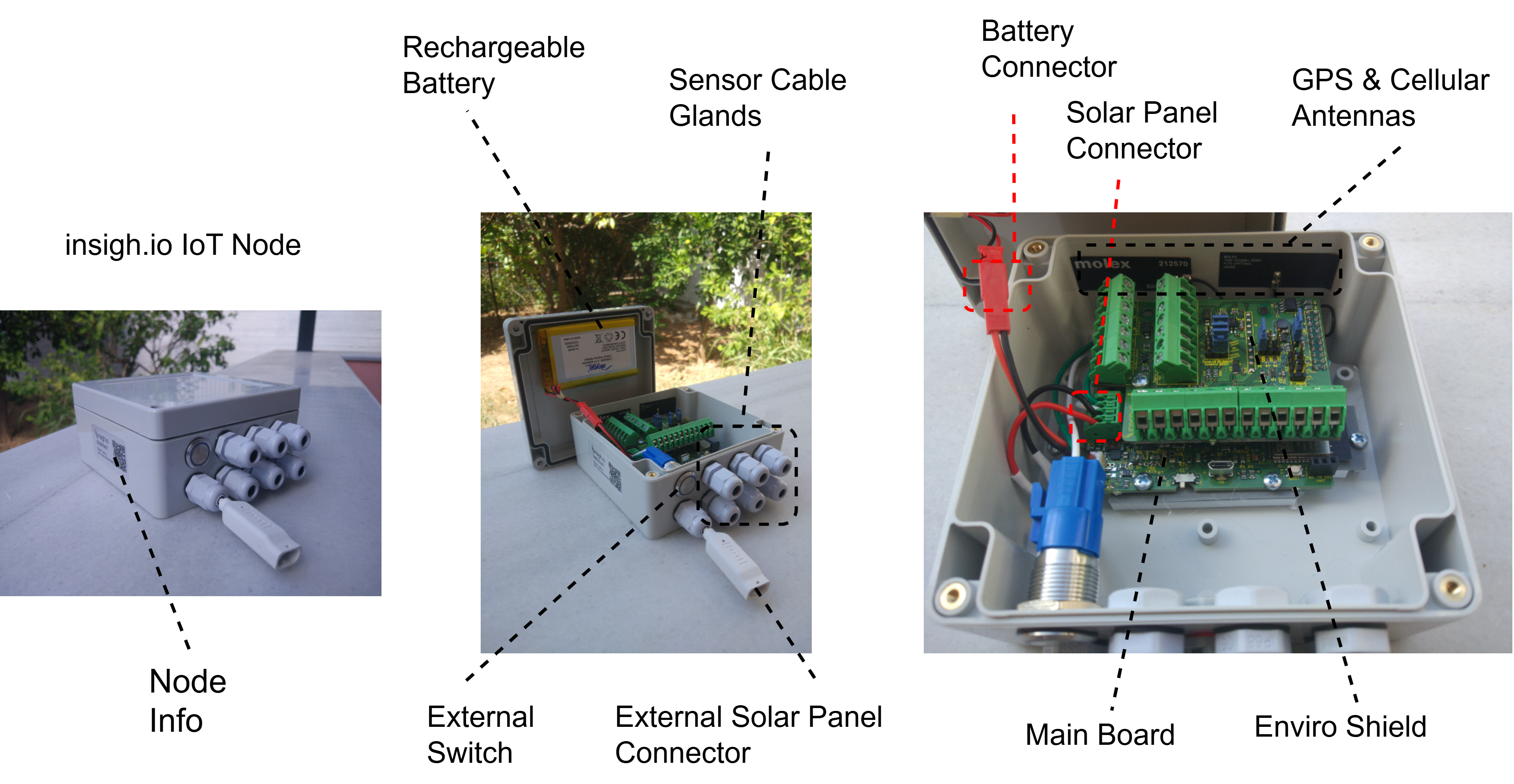
The key elements of a field setup are:
- The Main Board
- A Sensor shield (Enviro shield is used in this example setup)
- A custom weatherproof IP-rated enclosure suitable also for outdoor operation.
- A rechargeable battery, with typical capacity 4,000mAh
- An optional special IP-rated connector for the solar panel provided by insigh.io.
- Multiple cable glands for connecting the sensor cables to the Shield.
- An external switch to power on/off the node without opening the enclosure.
- A vent plug
- Flexible internal antennas
- A global SIM card with 500 MB data
Shield Configuration & Sensors Connection
In this tutorial we assume the user has a node with the Enviro Shield.
The setup steps may be groupped into 2 categories:
- Shield Configuration: In Stages 1-4, the user controls via jumpers certain parameters, i.e. how the sensors will be supplied and if the analogue sensor ports will sense voltage or current.
- Sensors Connection: In Stages 5-8, the user attaches the sensors to the various available ports.

Shield Configuration
Stage 1
Place a jumper to 5V, 9V or 12V position, to properly configure the voltage supply level. A common DC voltage level is applied across all PWR ports.
If no jumper is placed, the default DC voltage will be 5V.
Stage 2
- Place a jumper into the REG_ON position, in case you need a DC voltage level active even during deep sleep. This is neccessary -as an example- for speficic meteorological sensors who need to track rain and wind speed continously, rather than regularly. The only setback is the increased current consumption, leading to quicker battery drain. On average 3-5 mA are consumed for keeping the DC voltage active, instead of 150-200 uA in on-demand power excitation.
- If there is no such need the jumper should be placed betweem the middle and the bottom header pins. In this case the sensors will be excited only during node awakening.
There is no default option for this setting. If no jumper is placed the sensors will not be supplied.
Stage 3
Place a jumper into Always On or On Demand positions to control power excitation for SDI-12, Modbus RTU and Analogue Ports independently, during the awake period:
- Use Always On for continuous excitation during node awakening. If multiple sensors are configured this way they will be simultaneously active. For continuous excitation during deep sleep as well, you need to have REG_ON option selected (Stage 2).
- Use On Demand for controlled excitation via the firmware, which takes place at a specific part of the measurement cycle. This allows to save power and activate sensors serially.
There is no default option for this setting. If no jumper is placed the sensors will not be supplied.
Stage 4
Optionally place a jumper in the 4 x 4-20mA selector to turn the corresponding analogue input voltage port to a current sense port. If there is no jumper placed, the ports will measure by default the input voltage within the 0:3.3V range.
The 4-20mA selector essentially adds a shunt resistor with resistance 100Ω in the sensor-microcontroller path. The analogue sensor ports will still return voltage readings v. To directly obtain current sense readings the simple formula v/100 is used.
Sensors Connection
Stage 5
- Connect up to 2 x SDI-12 sensors in the available physical ports. These ports are not independent, i.e. PWR and DATA lines are connected. Hence, for having more than one SDI-12 sensors onboard, different addresses must be used.
- For connecting more than 2 sensors, an external combiner should be used. The firmware can handle up to ten SDI-12 sensors, as long as they listen in different addresses.
- The firmware allows to create multiple “virtual” sensors by defining commands/subcommands for each physical sensor. For example we can define 2 virtual sensors for an SDI-12 device listening on address 0, by defining an “M0” and and “M1” command.
Stage 6
Connect one (or multiple using an external combiner) Modbus RTU sensors/devices. The insigh.io node is considered the Master Device, so sensors are considered Slaves. The firmware allows to read multiple holding/input registers.
Stage 7
Connect up to 4 analogue sensors/signals in the corresponding ports. The voltage range is 0:3.3V and a 16-bit digitizer is used. If the maximum expected input voltage level is a priori known and is less than 3.3V (e.g. 0.512V), the user may configure the ADS Gain accordingly for increasing measurement precision.
Stage 8
Connect up to 2 x 2-wire Digital Outputs for Pulse Counting. This port allows to measure pulses generated by reed switches. It supports dry contacts with the IN port pulled down. A 3.3V excitation voltage is continuouysly on, even at deep sleep.
Final Remark
The hardware setup is ready. We can proceed with the firmware setup using the local configurator, but before that we need to do a few things in the Platform.