Advanced
Scope
Provide support for SDI-12, 4-20mA and pulse input sensors with flexible configurations. It is applicable to Agriculture & Environmental Monitoring applications.
General Information
| Host board | insigh.io main board |
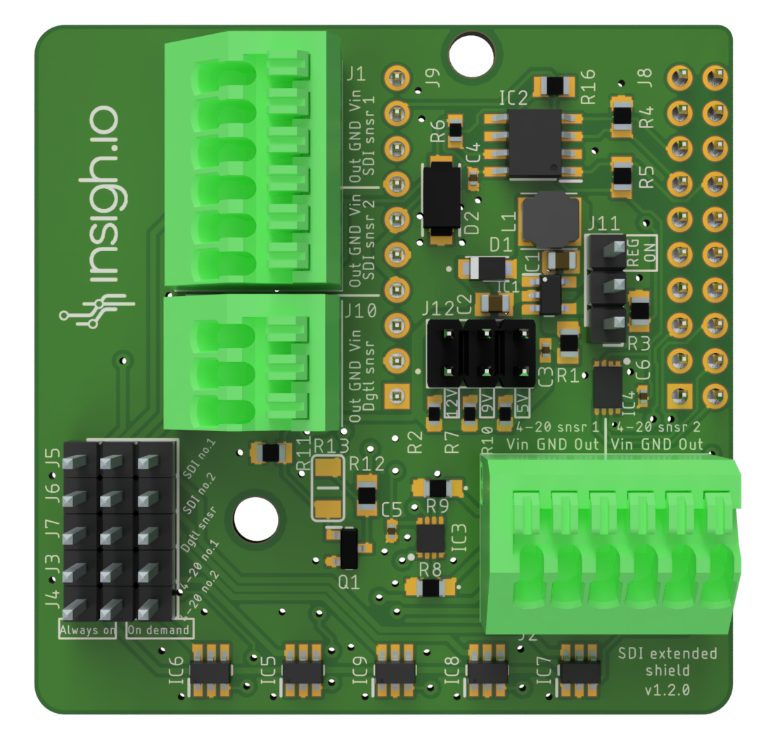
| Version | 1.2.0 |
| Supported Sensor Interfaces | 2 x SDI-12 & 2 x 4-20mA (2-wire or 4-wire) & 1 x Pulse Counter |
| Sensor Headers | 1x6-pin (SDI-12) & 1x6-pin (4-20mA) & 1x3-pin (Pulse Counter) |
| Supply Voltage | 5V/9V/12V DC: selected via jumper J12 (Default: 5V, when no jumper is placed) |
| Maximum Drawn Current | 250mA |
| Deep Sleep Current | 100 uA (typical) |
| Dimensions (L x W x H) | 50.17 x 49.53 x 16.7 mm |
| Weight | 10 g |
For new users, we recommend switching to the latest Enviro shield which supports all the interfaces of this shield in addition to extra interfaces.
Indicative list of tested sensors
- Soil Moisture (SDI-12): TEROS12 (METER)
- Water Level (4-20mA): Pressure Sensor PR26Y (KELLER)
- Rain (Pulse Output): Various Rain Gauge Tipping Bucket models (PRONAMIC)
Power
| Supply Voltage | 5V/9V/12V DC: selected via jumper J12 (Default: 5V, when no jumper is placed) |
| Power Modes | Board Power Mode: “REG ON” (Jumper J11) |
| Sensors Power Mode: “Always On” vs “On Demand” (Jumpers J3 & J7) | |
| Maximum Drawn Current | 250 mA |
Power Modes
Board Power Mode
This mode controls how the common sensor supply voltage (5V, 9V or 12V) is applied across all sensors.
There are 2 board “power” modes for the shield controlled via jumpers
- “Continuous” Mode: It applies continuous DC voltage even at deep sleep. This is required by some sensors for condensation avoidance (e.g. Oxygen Sensor SO-411 from Apogee) or special measurement procedure (e.g. Evapotranspiration Sensor which requires 30 min averaging or ATMOS41). To enable this, place the J11 jumper to “REG_ON” position.
- “Low-power” Mode: This is a mode optimized for energy consumption. To enable this place the J11 jumper to the bottom position. In this mode, the sensors are powered only during the micro-controller wake-up periods by enabling a special control pin from the firmware (IO37).
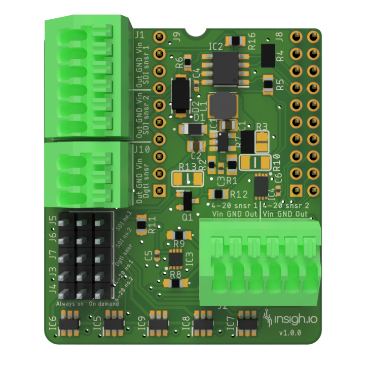
In version 1.0.0, control of board power is done via resistors (mounting/removing) as follows. For “Continuous” Mode” Mount R7 (1K) and Remove R10 (0 Ohm) & R3 (1M), whereas for “Low-Power” Mode” Remove R7 (1K) and mount R10 (0 Ohm) & R3 (1M).
Sensor Power mode
In addition, with the use of jumpers the user may control each sensor’s power mode independently.
There are 5 jumper sets for configuring the power mode of the 5 different sensor ports.
- J5 & J6 control the SDI-12 Sensor Port 1 and 2 respectively
- J3 & J4 control the 4-20mA Sensor Port 1 and 2 respectively
- J7 controls the single Digital Port
There are 2 sensor power modes:
- “Always On: The sensor is is powered continuously while the board is awake. Place the jumper in the left-center pins of the corresponding sensor jumper (J3-J7)
- “On demand: The sensor power is electronically controlled via the firmware. Place the jumper in the center-right pins of the corresponding sensor jumper (J3-J7). “On-demand” mode is the most energy-efficient one. The control pins are:
- SDI-12 Sensors: IO42 & IO48 for Port 1 & Port 2 respectively
- 4-20mA Sensors: IO7 & IO8 for Port 1 & Port 2 respectively
- Pulse Counter Sensor: IO6
Overview of Power Configuration Options
| Board Power Mode | Sensor Power Mode | Use Case |
|---|---|---|
| Continuous | Always-On | Sensor continuously powered during board awake and deep sleep. For example, this combination is applied for specific sensors needing heating. If more than one sensors are in this mode, they are concurrently active and can’t be controlled independently. |
| Continuous | On demand | As above, but sensors can instantaneously turned-off. |
| Low-power | On demand | Sensor powered for a limited time during board wake up period. Mode used for controlling sensors indepedently. For example, this combination can be used to have 2 SDI-12 sensors that don’t require continuous power and have the same address (e.g. 2 x TEROS-12 sensors at address 0). |
The combination of low-power board mode and always-on sensor mode, doesn’t have any practical usage.
SDI-12 Commands Support
[To be Added]
4-20mA Sensors Connection Instructions
Below you may find the proper connection instructions for 2-wire/4-wire sensors in case internal (own board) or external power supply unit is used. We assume that the power supply pin of the sensor is marked as “PWR” and the “measurement” pin of the sensor as “DATA”.
-
Sensor Type: 2-wire
- Power Supply: Internal
- Sensor PWR pin connected to VIN board port
- Sensor DATA pin connected to OUT board port
- Power Supply: External
- Sensor PWR pin connected to External Supply Positive Pin (+)
- Sensor GND pin connected to External Supply Negative Pin (-)
- Sensor DATA pin connected to OUT board port
- Power Supply: Internal
-
Sensor Type: 4-wire
- Power Supply: Internal
- Sensor PWR pin connected to VIN board port
- Sensor 1st GND pin connected to GND board port
- Sensor 2nd GND pin connected to same GND board port
- Sensor DATA pin connected to OUT board port
- Power Supply: External
- Sensor PWR pin connected to External Supply Positive Pin (+)
- Sensor 1st GND pin connected to External Supply Negative Pin (-)
- Sensor 2nd GND pin connected to GND board port
- Sensor DATA pin connected to OUT board port
- Power Supply: Internal
Pulse Counter Input
Dry contact reed switches are supported. The connection pins are as follows:
- VIN: Continuous 3.3V DC, even at deep sleep
- GND: Common Ground
- OUT: GPIO pulled-down, detecting edge.
Marking
| CE | ongoing, expected to be completed in Q1-2026 |
Changelog
| Version | Release Date | Comments |
|---|---|---|
| 1.3.2 | 04/10/2025 | Added pull-down resistor to stabilize SDI data bus. |
| 1.3.1 | 18/06/2025 | Changes in silkscreen (Vin–>Vcc, Out–>IN, added “Sensors power”). |
| 1.3.0 | 24/03/2025 | Voltage shifter of pulse counter removed. |
| Pull-down resistor added to GPIO of pulse counter. | ||
| 1.2.0 | 26/09/2024 | Set default sensor supply voltage level to 12V when no jumper is placed. |
| 1.1.0 | 17/09/2024 | Multiple Sensor Supply Voltage levels (5V,9V,12V) selectable via jumpers . |
| Regulator Mode Selector via Jumper. | ||
| 1.0.0 | 11/10/2023 | First stable version with all the interfaces available. |
| Regulator Mode (ALWAYS-ON vs ON-DEMAND) configurable via resistors. | ||
| Pulse Counter implementation includes an inverting voltage shifter and a non-inverting bypass via resistor. |