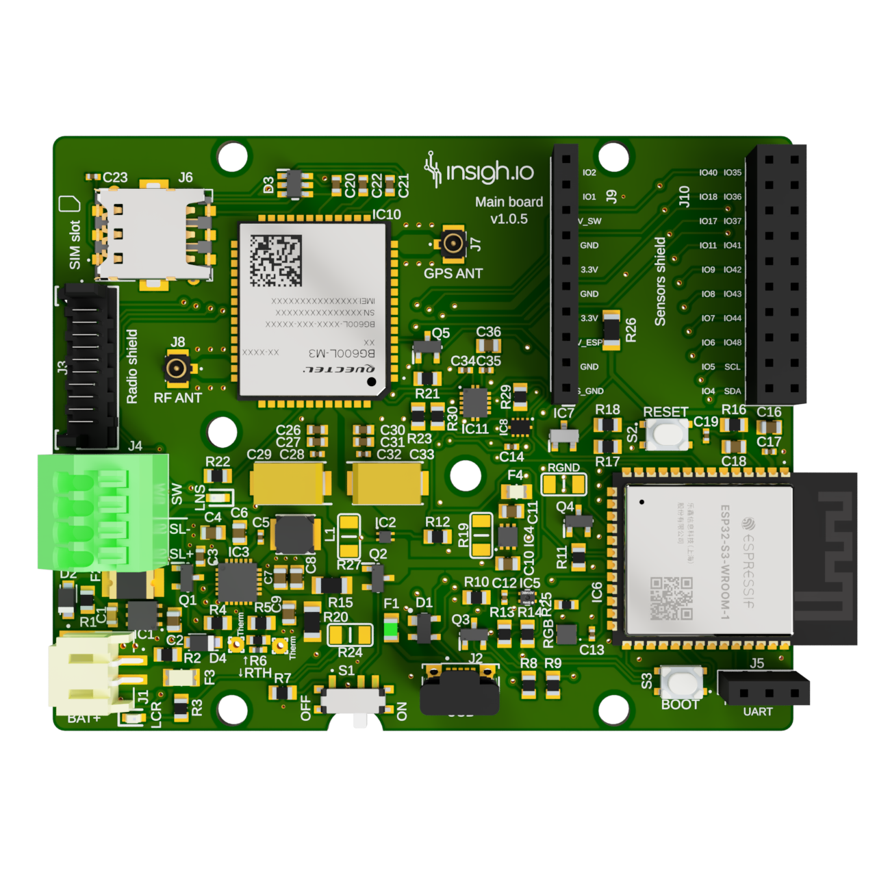
Main Board
| 1st version (part of certified bundle) |
Latest version |
 |
 |
|
|
| Versions |
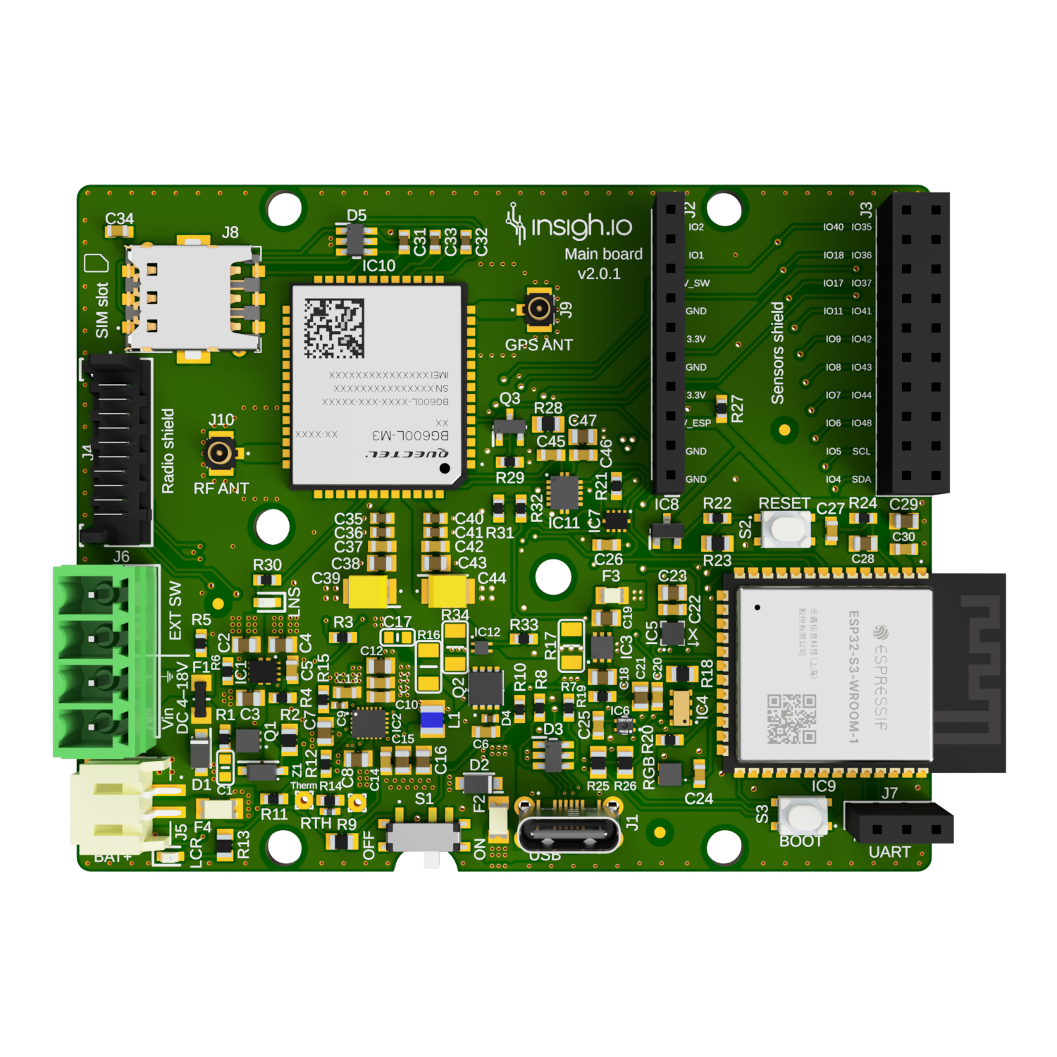
v2.0.1 (latest development version, certification pending) |
|
v1.0.5 (part of a certified bundle) |
| Microcontroller |
Espressif ESP32-S3 Module |
| Connectivity |
WiFi, Bluetooth, NB-IoT/LTE-M with GSM fallback (Nano-SIM Holder) |
| GNSS |
Embedded GPS, BeiDou, Galileo, GLONASS and QZSS |
| Power Supply |
Battery (primary & rechargeable), USB, Solar Panel |
| Onboard Sensors |
Temperature/Humidity (in all versions) and Accelerometer (only in v2) |
| Debugging |
Serial Port (UART) or USB for Debugging (in all versions) |
| Recovery |
External Clock (RTC) for maintaining timing during power failure (only in v2) |
| Switch |
Internal switch & support for external switch |
| Indicators |
Various LEDs |
| Software & Tools |
Micropython |
|
Open-source libraries & example scenarios @ Github |
|
Local Web Configurator through WiFi |
| Dimensions (L x W) |
77.47 (83.5*) x 62.23 mm (* with embedded wifi antenna) |
| Weight |
28 g |
| Deep Sleep Current |
100 uA [v1] / 70 uA [v2] (typical) |
| SKU |
INS-B-MAN |
Micro-Controller
|
|
| Model |
ESP32-S3-WROOM-1 |
| Flash |
8 MB/4 MB (Embedded) |
| Memory RAM |
2 MB (Embedded) |
Power Supply
| Source |
Version |
Port |
Input Voltage Range |
| Battery |
All |
JST |
1 x Rechargeable LiPo/Li-Ion 1S1C 3.7-4.2 V |
| Solar Panel |
v1 |
Terminal Block |
Min: 5.5 V, Typical: 6 V, Max: 7 V |
|
v2 |
Detacheable Plug |
Min: 4 V, Typical: 6 V, Max: 18 V |
| USB |
v1 |
Micro |
Min: 4.5 V, Typical: 5 V, Max: 5.5 V |
|
v2 |
Type-C |
Min: 4.5 V, Typical: 5 V, Max: 5.5 V |
Connectivity
|
|
| WiFi & Bluetooth |
Embedded on Micro-controller |
| Cellular (NB-IoT/LTE-M/GSM) |
Quectel BG600 Modem |
Operating Conditions
|
|
| Microcontroller Operating Voltage |
3.3 V |
| Rated Supply Voltage/Current |
Battery: 3.6-4.2 VDC 3A |
|
v1: DC-IN (Solar Panel): 6VDC 440mA |
|
v2: DC-IN (Solar Panel): 18VDC 440mA |
|
DC-IN (USB) 5VDC 440mA |
Switches
|
|
| S1 |
Controls power supply to the micro-controller (the battery charging process is not affected) |
| S2 |
Tactile switch for rebooting the micro-controller |
| S3 |
Tactile switch for activating the micro-controller’s bootloader (needed only for fw upgrade) |
| J4 |
Port for connecting external switch |
For controling the board using the External Switch, S1 (internal switch) should be in OFF state. If S1 is in ON state, the external switch is bypassed.
Indication LEDs
Charging State Indication (RED LED)
| Charge cycle state |
LCR LED |
| No input |
OFF |
| Temperature fault |
BLINKING |
| No battery |
BLINKING |
| Charging |
ON |
| Charge complete |
OFF |
Modem State Indication (RED LED)
| Modem state |
LCR LED |
| Disabled |
OFF |
| Network Search |
BLINKING SLOWLY (OFF most of the time) |
| Idle |
BLINKING SLOWLY (ON most of the time) |
| Transferring Data |
BLINKING QUICKLY |
Operational State Indication (RGB LED)
| RGB LED Color & Status |
Operational |
| blinking random colors |
File system optimization procedure (firmware version v2.11.0+) |
| blink white |
Initializing device |
| blinking purple |
Web UI waiting for client (only after hard reboot) |
| solid purple |
Web UI with connected client (only after hard reboot) |
| solid blue |
Executing enabled measurements |
| solid red |
Connecting to network |
| solid green |
Network connected, uploading data |
| solid yellow |
Uploading data failed |
| off |
Deep sleep |
On-board diagnostics & debug
|
|
| Battery Voltage |
Accurate Measurement of battery voltage even at charging state |
| Environment Conditions |
1 × on-board temperature/humidity Sensor (based on the SHT40 IC) |
| Movement |
1 x on-board accelerometer (based on the LIS2DW12 IC) - only in v2 |
| Location |
Through embedded GPS (only works outdoors) |
| Debug Port J5 |
Standard Serial Port (needs an external USB-to-Serial adapter to connect to PC) |
| Debug Port J2 |
Standard Serial Port |
| Timing Recovery |
External RTC powered by the battery. In case of modem/power failure it can keep the timing. Resets if battery removed - only in v2 |
Special Configurations
|
|
| Bypass Charger (only in v1) |
By default R20 (0 Ohm) is not mounted and R15 (0 Ohm) is mounted. In case you need to bypass the charger and power the board solely through a battery then R15 should be removed and R20 should be mounted |
| Micro-controller Power Line Break |
By default R26 (0 Ohm) is mounted. In case you need to break the micro-controller’s power line (e.g. for adding a special circuit like a watchdog) then this should be removed |
Protection
|
|
| Overcurrent |
4 x Resettable Fuses for battery, solar panel, USB port, and 3.3V regulator paths |
| Charge at low/high temperatures |
1 x Thermistor disabling charging beyond temperature limits |
Expansion Ports
Sensor Expansion Port
|
|
| Port |
J9-J10 |
| Type |
1 x Single-Row & 1 x 2-row 10-pin Female Socket Header |
| Usage |
Attach insigh.io sensor shields or custom applications in breadboards |
Connectivity Expansion Port
|
|
| Port |
J3 |
| Type |
1 x Custom 10-pin Connector (Part number: 90325-0010) compatible with Ribbon Flex Cable (Part number: 92317-1012) |
| Usage |
Attach insigh.io connectivity shields |
Pinouts
Sensor Expansion Port
| J9 |
J10(L) |
J10(R) |
| IO2 |
IO40 |
IO35 |
| IO1 |
IO18 |
IO36 |
| V_SW |
IO17 |
IO37 |
| GND |
IO11 |
IO41 |
| 3.3V |
IO9 |
IO42 |
| GND |
IO8 |
IO43 |
| 3.3V |
IO7 |
IO44 |
| V_ESP |
IO6 |
IO48 |
| GND |
IO5 |
SCL |
| S_GND |
IO4 |
SDA |
Orientation as in the board picture. IOs naming refer to corresponding ESP32-S3-WROOM-1 IOs.
Connectivity Expansion Port
| J3 |
|
| 1 |
GND |
| 2 |
3.3V |
| 3 |
IO40 |
| 4 |
IO18 |
| 5 |
IO35 |
| 6 |
IO36 |
| 7 |
SDA |
| 8 |
UART1_TX |
| 9 |
SCL |
| 10 |
UART1_RX |
- GND: Common Ground
- 3.3V: Used for powering the modem of the shield
- IO40, IO18, IO35, IO36: Free digital pins to use in the shield as input/output
- SDA/SCL: Exposed I²C bus to accomodate compatible devices
- UART1_TX/UART1_Rx: Exposed Serial Bus to accomodate compatible devices (modem, GPS, etc.)
Cerfification
|
|
| CE |
Latest v1 version is part of a certified bundle. EU Declaration of Conformance is available upon request. |
|
Certification for v2 is ongoing |
Changelog
| Version |
Release Date |
Comments |
| 2.0.1 |
08/02/2026 |
Minor component alignments |
| 2.0.0 (Major Revision) |
21/12/2025 |
DC input for solar port extended to 18V, accompanied by power path redesign and new charging IC |
|
|
Integration of dedicated RTC and Accelerometer |
|
|
Ports change: USB port changed to Type-C & Solar/Switch connector changed to detacheable |
|
|
Improvements in power consumption |
| 1.0.5 |
08/12/2025 |
Part of a certified bundle; Correct footprint of fuse |
| 1.0.4 |
05/03/2025 |
Change resettable fuses to tolerate higher voltages |
| 1.0.3 |
20/08/2024 |
Minor mechanical changes (holes standoffs) |
| 1.0.2 |
31/12/2023 |
Fix increased deep sleep current due to external switch pulled down resistor |
| 1.0.1 |
17/03/2023 |
Added resettable fuses to solar panel, battery and the output of the 3.3V regulator; Change connector for connectivity shield |
| 1.0.0 |
29/06/2022 |
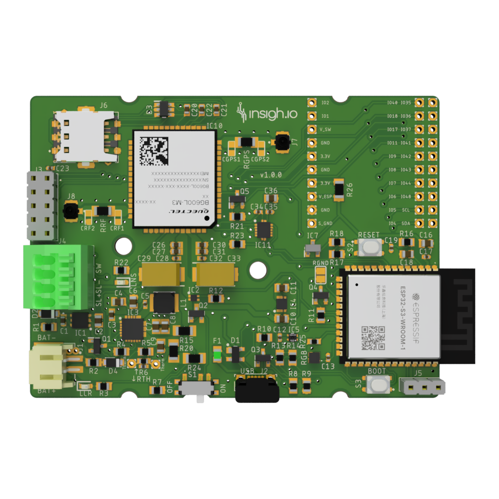
First stable version with ESP32-S3 & Sensor Expansion Port |