Enviro
| 1st version (part of certified bundle) |
Latest version |
 |
 |
Scope
A versatile shield providing support for multiple SDI-12, Modbus-RTU, high-precision Analogue/4-20mA and Pulse ouput sensors/devices. It is mainly applicable to agriculture and environmental monitoring applications requiring the simultaneous connection of many diverse sensors.
|
|
| Host board |
insigh.io main board |
| Versions |
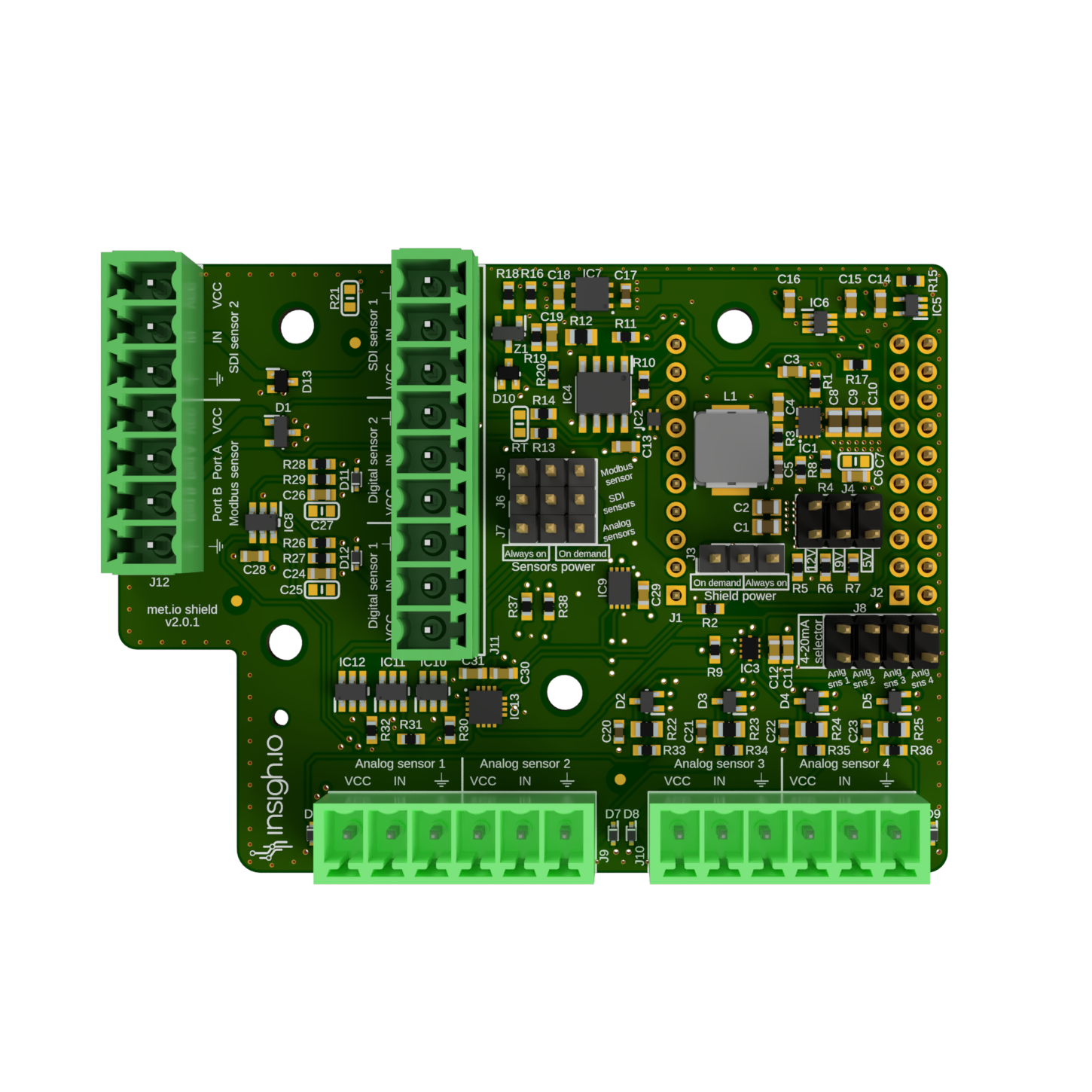
v2.0.1 (latest development version, certification pending) |
|
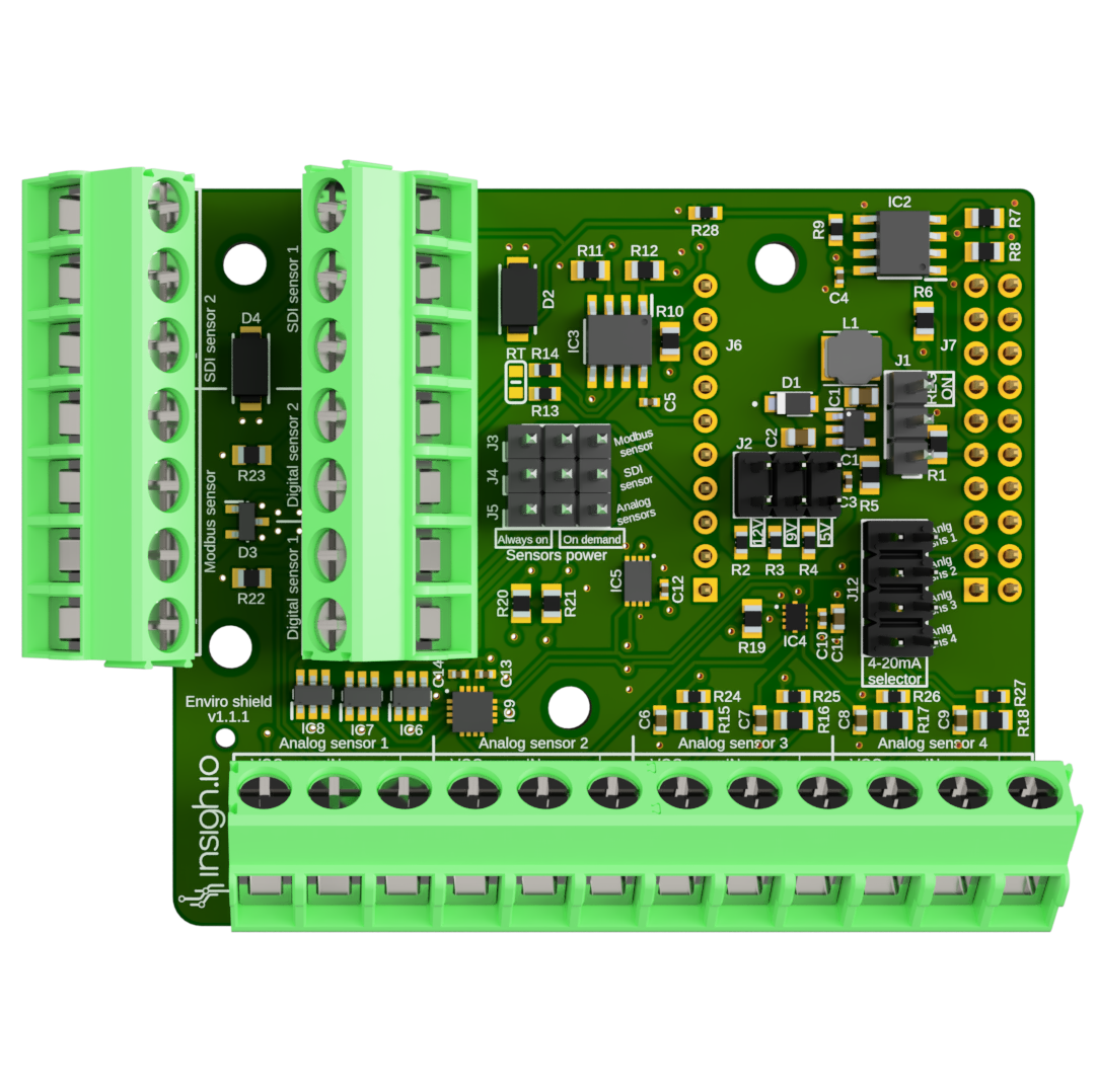
v1.1.1 (part of a certified bundle) |
| Supported Sensor Interfaces |
2 x SDI-12 & 1 x Modbus-RTU & 4 x Analogue 16-bit / 4-20mA & 2 x Pulse Counter |
| Sensor Headers |
2x7-pin (SDI-12/Pulse Counters & SDI-12/Modbus-RTU) & 1x12-pin (Analogue 0-3.3V / 4-20mA) |
| Supply Voltage |
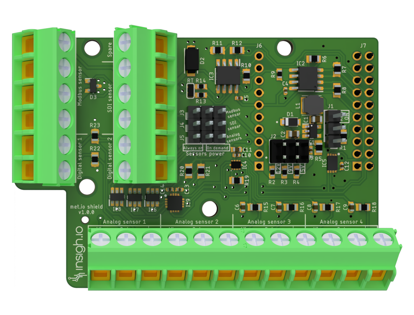
5V/9V/12V DC: selected via jumper J12 (Default: 5V, when no jumper is placed) |
| Deep Sleep Current |
70 uA [v2] / 100 uA [v1] (typical) |
| Dimensions (L x W) |
75.57 x 55.44 mm |
| Weight |
16 g |
| Software Support |
To use v2 shield you need at least insighioNode firmware version 3.9.0 |
Indicative list of tested sensors
- Weather Station: (SDI-12): ATMOS41 (METER), WS650 (Kisters)
- Air Quality (Modbus RTU): PMBsense
- Industrial PLC Control (Modbus RTU): IDEC
- Wind Direction (Analogue): 7911 (DAVIS), 4.3140.51.010 (THIES)
- Air Quality (Analogue): Edinburgh Guardian NG
- Rain (Pulse Output): Various Rain Gauge Tipping Bucket models (PRONAMIC)
Power & Sensor Modes
|
|
| Supply Voltage |
5V/9V/12V DC: selected via jumper J2 (Default: 5V, when no jumper is placed) |
| Power Modes |
Board Power Mode: “REG ON” (Jumper J1) |
|
Sensors Power Mode: “Always On” vs “On Demand” (Jumpers J3,J4,J5 for SDI-12/Modbus-RTU/Analogue) |
| Sensor Modes |
Analogue/4-20mA Mode: Each of the 4 (0:3.3V) analogue channels can be turned to a 4-20mA channel by using a jumper in J12 |
| Maximum Drawn Current |
250 mA |
Power Modes Analysis
Board Power Mode
This mode controls how the common sensor supply voltage (5V, 9V or 12V) is applied across all sensors.
There are 2 board “power” modes for the shield controlled via jumpers
- “Continuous” Mode: It applies continuous DC voltage even at deep sleep. This is required by some sensors for condensation avoidance (e.g. Oxygen Sensor SO-411 from Apogee) or special measurement procedure (e.g. Evapotranspiration Sensor which requires 30 min averaging or ATMOS41). To enable this, place the J1 jumper to “REG_ON” position.
- “Low-power” Mode: This is a mode optimized for energy consumption. To enable this place the J1 jumper to the bottom position. In this mode, the sensors are powered only during the micro-controller wake-up periods by enabling a special control pin from the firmware.
Sensor Power mode
In addition, with the use of jumpers the user may control each sensor’s power mode independently.
There are 5 jumper sets for configuring the power mode of the 3 different sensor technology ports.
- J3 controls the Modbus RTU Port
- J4 controls the 2 (connected) SDI-12 Ports
- J5 controls the 4 Analogue/4-20mA Port
There are 2 sensor power modes:
- “Always On: The sensor is is powered continuously while the board is awake. Place the jumper in the left-center pins of the corresponding sensor jumper (J3-J5)
- “On demand: The sensor power is electronically controlled via the firmware. Place the jumper in the center-right pins of the corresponding sensor jumper (J3-J5). “On-demand” mode is the most energy-efficient one.
Overview of Power Configuration Options
| Board Power Mode |
Sensor Power Mode |
Use Case |
| Continuous |
Always-On |
Sensor continuously powered during board awake and deep sleep. For example, this combination is applied for specific sensors needing heating. If more than one sensors are in this mode, they are concurrently active and can’t be controlled independently. |
| Continuous |
On demand |
As above, but sensors can instantaneously turned-off. |
| Low-power |
On demand |
Sensor powered for a limited time during board wake up period. Mode used for controlling sensors indepedently. |
The combination of low-power board mode and always-on sensor mode, doesn’t have any practical usage.
Sensor Ports
SDI-12
|
|
| Number of Physical Sensors |
2 x Connected Ports (VCC for sensor power supply, IN for sensor data, GND for sensor ground) |
| Number of Supported Sensors (SW/HW) |
Up to 10 sensors with external combiner |
| Commands |
SDI-12 Commands Implementations: Measurement (C, M, R), Verification (V), Extended (X) and additional (e.g. M1, C1) |
Modbus-RTU
|
|
| Number of Physical Sensors |
1 x Physical Port with 4 inputs (VCC,A,B,GND) |
| Number of Supported Sensors (SW/HW) |
Multiple slaves with external combiner |
| Software Support |
Configurable System Settings: Baud rate, Data bits, Stop bits, Parity |
|
Configurable Slave(s) Settings: Address, Register, Register Type (Holding/Input), Data Format (Integer, Float), Measurement Precision |
Analogue/4-20mA
|
|
| Number of Physical Sensors |
4 x Physical Ports with 3 inputs each (VCC,IN,GND), where VCC is common across all ports |
| Analogue Voltage Readings |
Configurable Dedicated ADS 16-bit Voltage Range: 0:256mV, 0:512mV, 0:1.024V, 0:2.048V, 0:3.3V |
| 4-20mA Mode |
Current to Voltage transformation Resistor: 100 Ohm |
Pulse
v1
|
|
| Number of Physical Ports |
2 x Physical Ports with 2 inputs each (VCC, IN) |
| Implementation |
VCC connected internally to 3.3V / IN pulled down |
| Connections |
Support 2-wire pulse output devices only (no external voltage supply needed). Sensor cables can be connected to the VCC and IN inputs either way. |
v2
|
|
| Number of Physical Ports |
2 x Physical Ports with 3 inputs each (VCC, IN, GND) |
| Implementation |
VCC connected internally to 3.3V / IN pulled up / GND to common Ground |
| Connections |
Support pulse output devices requiring also external supply. For 2-wire devices connect one cable to IN (since it is pulled up) and the other to GND. |
Cerfification
|
|
| CE |
Latest v1 version is part of a certified bundle. EU Declaration of Conformance is available upon request. |
|
Certification for v2 is ongoing |
Changelog
| Version |
Release Date |
Comments |
| 2.0.1 |
13/04/2026 |
Enable fully switching off regulator output at deep sleep. |
| 2.0.0 |
19/03/2026 |
Enhanced front-ends for analog and digital sensors. |
|
|
Changed sensor headers to detacheables (plugs) |
|
|
New SDI-12 implementation at hardware level |
| 1.1.1 |
04/10/2025 |
Added pull-down resistor to stabilize SDI data bus. |
|
|
Part of a certified bundle. |
| 1.1.0 |
13/06/2025 |
Added a second SDI-12 port |
|
|
Added 4-20mA selector for the analogue ports |
|
|
Changed naming of ports: VCC for sensor supply voltage, IN for sensor data signal |
| 1.0.0 |
12/03/2025 |
First stable version with 1 x SDI-12 port, 1 x Modbus RTU port, 4 x Analogue ports, 2 x Pulse Input ports |
|
|
Ports naming: VIN for sensor supply voltage, OUT for sensor data signal |